ADSP-BF533 is an awesome fixed-point DSP. However it has only one UART...
ADSP-BF706 is another awesome chip. However it has only two UARTs...
What can we do?
I've been using Blackfin DSPs in my projects for quite a long time. Sometimes I need more UARTs. Fortunately, by using the synchronous serial ports(SPORTs) on Blackfin DSPs, this can be easily accomplished. An Engineer To Engineer Note(EE-191) provided by Analog Devices introduced how to implement UART using SPORTs on SHARC DSPs. However they did not mention Blackfin DSPs. So this will be a "how-to" article, intended to accomplish the following requirements:
        UART Format:
        Data bit  : 8
        Parity bit: N
        Stop bit  : 1
        Baud rate : Arbitrary
    On ADSP-BF533
    Using DMA, full-duplex
Theoretically, it is possible(and easy) to implement other UART format on different Blackfin DSPs.
Before reading this article, I recommend you to read ADI's EE note(EE-191) first. It was intended for SHARC DSPs, but most of the theorem also applies to Blackfin DSPs.
As described in the EE note, DTx and DRx are used as TX and RX. Also, RFSx needs to be connected to DRx to provide a "trigger" signal so that the SPORT knows when to start receiving. Here, I'm using primary DTx (DTx PRI) and primary DRx (DRx PRI). Transmitting clock and receiving clock are left unconnected.
    +------------+            +------+
    |  BLACKFIN  |            | UART |
    |------------|            |------|
    |   ...      |            | ...  |
    |   TCLKx    |            |      |
    |   TFSx     |            |      |
    |   DTx PRI  |>---------->| RX   |
    |   DTx SEC  |            |      |
    |   DRx PRI  |<---+------<| TX   |
    |   DRx SEC  |    |       |      |
    |   RFSx     |<---        |      |
    |   RCLKx    |            |      |
    |   ...      |            | ...  |
    +------------+            +------+
Transmitting is rather straight forward, there is not much difference between SHARC and Blackfin.
What we need to do is set the SPORT's baud rate to be the UART's baud rate, also set SPORT to transmit LSB first. Since we hav 8 data bits, and 1 stop bit, UART requires a total of 10 bits(additional 1 start bit). Therefore, we can set our SPORT to transmit 10 bits and add 1 start bit before its LSB and 1 stop bit after its MSB. We can implement this using C, just some 'shift' and 'or' operations.
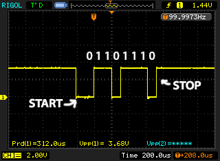
Transmitting a char 'v'(ASCII: 118, hex: 0x76, bin: 0111 0110):

Receiving is a bit tricky. As UARTs are asynchronous, we cannot guarantee that the phase of the transmitter and our DSP is synchronised. Therefore, oversampling is necessary in order to properly re-construct our data. According to Analog Devices' EE note, 3x oversampling is used. Therefore, if we have a baud rate of 9,600 bps, we need the sampling frequency of our DSP to be 3x faster. Which means that we need to set our SPORT speed to 28,800 bps. We can simply set the divisor register(SPORTx_TCLKDIV) of our SPORT to an appropriate value. This value is calculated using the following formula:
               DSP Core Clock Frequency
    DIV = -------------------------- - 1
                   6 x BPS
Now, since UART signal stays high at idle, we need to set RFSx to be active low and start clocking upon falling edge.
Since we have 8 data bits, 1 stop bit, we have a total of 9 bits. By a 3x over sampling, we have 27 bits. We also have 2 leading extra bits, which is our frame sync. This means, we need to set our SPORT to be receiving 29 bits of data.
    SPORT Rx Settings:
        Baud rate: 3 x UART Baud Rate
        RFSx     : Active low
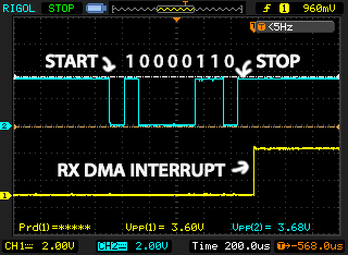
Let's capture some actual data. Here is a char 'a'(ASCII: 97, hex: 0x61, bin: 0110 0001):
Notice that UART transmits LSB first.
CH1: SPORT DMA receive interrupt
CH2: SPORT DRx

Now our SPORT reads 0x7000fc7. Let's see how we can get our data:
We know that the first 2 bits are frame sync, which we don't need. Then the following 27 bits are our oversampled data, followed by 3 useless bits. If we can some how extract the "middle" bit from those oversampled bits, and deposit them to our destination, then we can have our desired data. As illustrated by the following graph:
        SPORT: 0x7000fc7

    bit 28 >-----------------------------> 0
        0 0111 0000 0000 0000 1111 1100 0111
            ^   ^   ^  ^   ^   ^   ^  ^   ^
            |   |   |  |   |   |   |  |   |
    bit     25  22  19 16  13  10  7  4  (1)
    ----    1   0   0  0   0   1   1  0  (1)(stop bit)
    UART
    bit    0 <----------------------< 7

    UART data = 0b0110 0001
Let's see what we need to do:
        Extract the 25th bit from SPORT, put it to LSB    (UART),
    Extract the 22nd bit from SPORT, put it to 1st bit(UART),
    Extract the 19th bit from SPORT, put it to 2nd bit(UART),
    ...
This could be done in C easily, but since we're using DSP, there's a better way to go.
In the EE note, two special instructions on SHARC are used: fext and fdep. 'fdep' deposits a field from an register to another register, 'fext' extracts a field from an register to another register. We have similar instructions on Blackfin as well, they are 'extract' and 'deposit':
    dest_reg = EXTRACT ( scene_reg, pattern_reg ) (Z)
    dest_reg = DEPOSIT ( backgnd_reg, foregnd_reg )
Now, we can do this:
    R3.L = 0x1901; /* bit 25 -> UART bit 0 */
    R2 = extract(R0, R3.L)(Z);
    R2 <<= 16; R2.L = 0x0001;
    R1 = deposit(R1, R2);

    R3.L = 0x1601; /* bit 22 -> UART bit 1 */
    R2 = extract(R0, R3.L)(Z);
    R2 <<= 16; R2.L = 0x0101;
    R1 = deposit(R1, R2);

    ...
It seems we have more instructions than the SHARC implementation. But anyway, Blackfin DSPs are faster than SHARC DSPs.
Complete code segment
Available on Bitbucket snippets(Blackfin assembly)By using SPORT on Blackfin DSPs, we can implement a high performance full-duplex UART. The flexibility of SPORT and DMA minimizes the overhead. EXTRACT and DEPOSIT instructions are used on Blackfin DSPs to provide optimal performance.
1. "Implementing a Glueless UART Using The SHARC® DSP SPORTs":
    http://www.analog.com/media/en/technical-documentation/application-notes/EE191.pdf

2. "ADSP-21160 SHARC® DSP Instruction Set Reference":
    http://www.analog.com/media/en/dsp-documentation/processor-manuals/ADSP-21160_isr_rev2.1.pdf

3. "Blackfin® Processor Programming Reference":
    http://www.analog.com/media/en/dsp-documentation/processor-manuals/Blackfin_pgr_rev2.2.pdf