In most servo motor control applications, the rotor angle and rotor angular velocity are the most important information require to achieve a decent control. The angular position of the rotor can be easily obtained using an encoder, and they are pretty accurate. However, the angular velocity of the rotor is relatively difficult to obtain. The easy way is to calculate the differentiation of the angular position of the rotor. This approach works fine when the angular velocity is relative high, but when the motor is running at low speed, or even zero speed, massive noise will be introduced to the control loop. In this case, the angular velocity is essentially contaminated by quantization noise.
A better approach is introduced by TI on their Youtube channel. A "velocity observer", or alpha-beta filter, utilizes two integrators to obtain the angular velocity and angular acceleration from position signal. More details can be found in their video here. Alpha-beta filters are essentially simplified Kalman filters. For servo applications, alpha-beta filters may not be enough since the angular velocity could change rapidly depending on control signals.
Consider the following equations:
$$\theta (t) =\int \omega (t) \, dt$$
$$\omega (t) =\int \alpha (t) \, dt$$
where $\theta$ is the angular position, which is directly measured using an encoder, $\omega$ is the angular velocity and $\alpha$ is the angular acceleration.
Thus, we can write the following state variable for our Kalman filter:
$$X (t)=\left(
\begin{array}{c}
\theta (t) \\
\omega (t) \\
\alpha (t) \\
\end{array}
\right)$$
Since the integral of angular acceleration is angular velocity, and the integral of angular velocity is angular position, we can write out prediction matrix as following:
$$A=\left(
\begin{array}{ccc}
1 & \frac{\text{dt}^2}{2} & 0 \\
0 & 1 & \frac{\text{dt}^2}{2} \\
0 & 0 & 1 \\
\end{array}
\right)$$
where $dt$ is the sampling interval.
The measurement matrix $H$ is just an identity matrix since our measurement is our state.
The control matrix $B$ can be used as a feed forward term to reduce phase delay, this will be discussed in the later articles about the actual control loops. Here, we set all its elements to zero.
Tuning $Q$ and $R$ matrix
There's no absolute standard for tweaking them. The following image shows the step response with different $Q$ and $R$ settings. Like any other low pass filters, this is essentially a trade off between phase delay and noise floor. The standard deviation provided by the sensor manufacturer is a good starting point.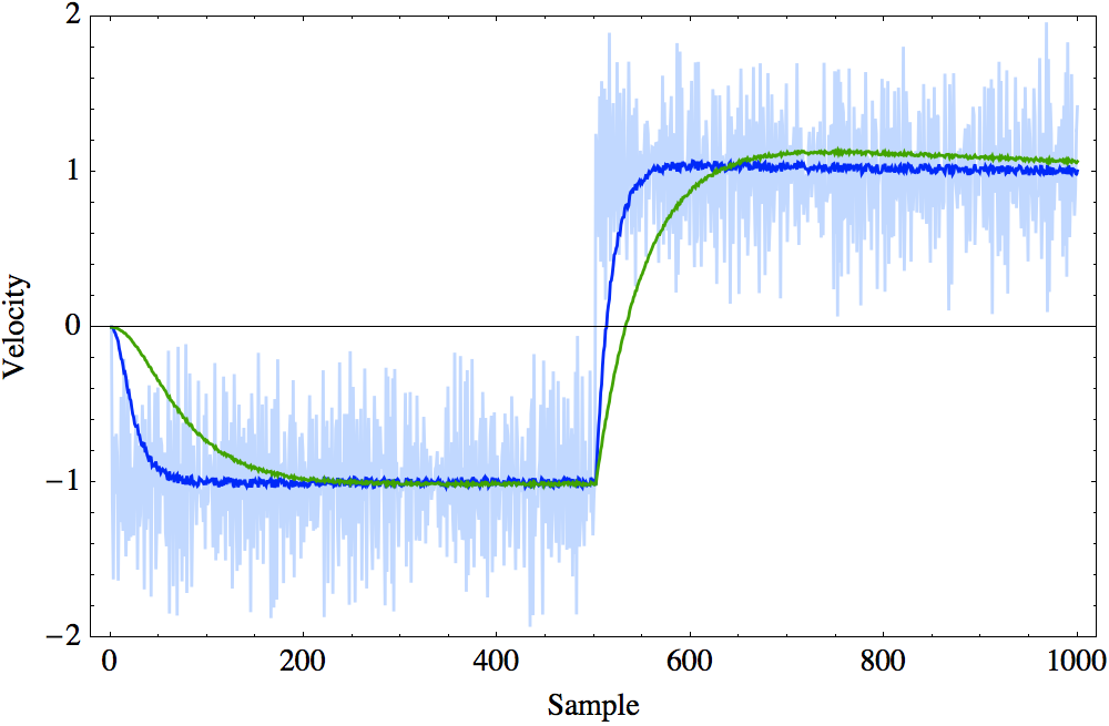
1. "An Introduction to the Kalman Filter":
    http://www.cs.unc.edu/~welch/media/pdf/kalman_intro.pdf

2. "Field Oriented Control of Permanent Magnet Motors":
    https://www.youtube.com/watch?v=cdiZUszYLiA